The need for aftermarket gauges in these vans is higher than any other vehicle I’ve owned. This stems from several root issues. For example, the wiring system in these vans was poorly engineered (for Toyota’s standards anyway) and electrical issues, especially gremlins in the charging circuit, are very common. A voltmeter can help identify when issues are present. Another weak link in these vans is the cooling system, due to the lack of airflow to the radiator and engine bay. “Heat soak” is a common issue in these vans where the fuel vaporizes and you get “vapor lock” and cant start the engine. Overheating is also very common. A more accurate temperature gauge the stock dash gauge is almost a necessity! Another issue I’ve personally faced on top of these too is poor gas mileage. Because of the underpowered motor, I was always pedal-to-the-metal, forcing the computer to run the fuel rich all the time (especially at freeway speeds.) Installing an air/fuel ratio gauge has helped a lot in aiding my driving habits, as well as identifying a bad TPS that was contributing to the bad mileage. Lastly, an oil pressure gauge would help me keep a much better eye on my engine’s health and performance.
All in all, as you can see from my experience, I felt a great need to install some gauges and get more feedback on the different systems in the van. It’s been a highly valuable modification that was well worth the investment. I strongly recommend those that own vans (especially if you have issues with the oil/fuel/electrical/cooling systems) to immediately get some gauges in there and give yourself (or your mechanic) the tools to help troubleshoot problems, find solutions, and help the van run in tip-top shape. After all, we all want to put another 300,000 miles on these right?
I’ll link to the parts and tools on Amazon I used for this setup (Try Prime Discounted Monthly Offering) You can adapt these to use whatever you’d like, but I found this setup to be the one I liked the most and met my criteria. You can follow my setup exactly or use this as a guide and inspiration for your own ideas. Creativity rocks. If you end up doing something different, detail it in the comments so other readers can be inspired!
Parts List:
Prosport EVO Series Gauges (I chose all digital gauges, much easier to install):
Wideband Air/Fuel (green/white or red/blue or universal) (this requires a second, special O2 sensor be installed. I chose a narrowband meter instead, because its cheaper and I didn’t need the accuracy of a wideband. However, you may want this extra accuracy, or to have all the gauges match)
Autometer narrow band air/fuel ratio gauge (compatible with factory O2 sensor)
Disclaimer: unfortunately I didn’t document this well enough at the time I actually did it, so there are some details (like some photos, wire lengths, etc.) omitted for the moment. Getting it would require me disassembling it all again. Next time I take the dash apart, I will try to get the missing info and photos and update this post with more detail. (It should still be very reasonable to do this using this post and some of your own problem solving ability!)
Remove the Dash
You’ll want to start by following my post on removing the dash. Its easiest if you just remove everything you can, so you have more space to work. I removed the whole thing entirely.
Mount Gauges into Pods
Once the dash is off, insert the gauges into the pods. The gauge comes attached with some nuts and a plate that allow you to attach and tighten the gauge into the pod. My gauges also came with a small plastic “key” that can be used to adjust the brightness. I turned mine all the way down and then slightly up a hair from there. I don’t like mine being too bright so I preferred to have them almost as dim as possible.
This is not from the van, but illustrates how its going to look.
Optional: Tidy up the wiring
Once that is done, cut the cable sleeve to the length you need and use a lighter or heat to singe the end to keep it from fraying (like you would with rope.) I drilled a hole in the back of the center pod then bundled the wires together in the cable sleeve and ran it through the hole I drilled. Make sure you keep track of which wires go to which sensor. You dont want to accidentally mix this up or youll have to undo this all. Bundling the wires and running them through this sleeve is optional, but I felt it helped make the install neater and keep all those wires tucked together and under control. Unfortunately I didnt document this part well, but its really done to your liking so its up to you how you want to run the wires and dress them.
Optional: Wire up the connector harnesses
Take and strip back the ends of the gauge wires, and select the appropriate connector. This kit includes 1, 2, 3, 4, 5, and 6-pin connectors. So if the gauge has 3 wires, youll use a 3-pin connector. Crimp the connector to the end of the wire and insert the connector into the plastic housing. This part I unfortunately didn’t document very well, but its fairly straightforward and takes a relatively small amount of problem solving. If you don’t use these connectors I’d strongly recommend formulating some way to be able to easily disconnect the wiring, because the gauges will be mounted to the dash and will have to come off with the cluster if you ever remove it again (fair warning: you will!)
Run the wiring
You can then pass the cables through the seam of the dash near the windshield. You can also drill a hole in the instrument panel dash piece and pass the wires directly through that, but I would rather drill the replaceable dash pod than mess up my factory dash. Set the pod and run the wiring down.
For the single pod, where I installed it, I didnt have to drill a hole because the bottom opening of the pod overlaps over the dash. Since it didnt sit flush, I just dropped the wires straight down through the opening.
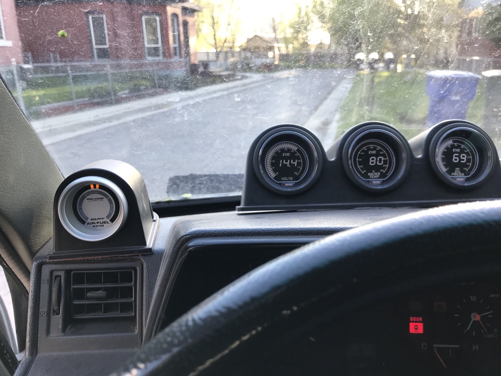
The gauges should have included installation instructions and wiring diagrams that tell you where to connect the various wires, so I won’t go into a lot of detail here since every gauge is different. In my case with these Prosport gauges, there was a red and white wire which ran to accessory power, an orange wire that ran to the headlight power, a black for ground, and 1-3 wires that ran to the corresponding sensor (O2 sensor, oil pressure sensor, coolant sensor).
You’ll have to get the 22-gauge wire in the corresponding color, determine the lengths you’ll need (always cut more than you need if you arent sure it’ll be long enough), then crimp and attach the other end of the harness connectors. You can plug them in to the wires running from the gauge.
Power wires
To connect the power and headlight wires, You can run them straight across, behind the stereo to the fusebox. From there you can tap the red and white connectors from all 4 of the gauges (except to the volt gauge, this should go direct to battery) to one crimp connector to the add-a-circuit. Or, you can use 2 add-a-circuit connectors and run all the red wires into one and all the white wires into the other. This is what I did, since I had difficulty fitting them all into one connector properly. Plug the add-a-circuit fuse holder(s) into a slot that runs accessory power. I used the fuse slot for the stereo circuit, for example. Then I ran all the orange wires together in a third add-a-circuit and installed that in another accessory fuse slot. You can tape/cap off the orange wires if you want, but in order to get the color change with the headlights on you’ll want to. The diagram that came with the gauges should tell you what to do depending on what color you want at day/night. I had the gauges white by standard, and the green come on with the headlights at night, because the green was easier on the eyes at night time.
Ground wires
A nice ground location behind the dash to the right of the steering column.
For the ground wires, I ran those straight back to a nut behind the steering column area that I thought that would work as a ground point. Where you ground is flexible. Just strip back the ground wires, twist them together, and crimp a ring terminal to the bundle. There are many metal-to-metal bolts and nuts you can attach the ground connection to. Find one that works best for you.
Sensor wires
I ran my wiring through this plug from the interior, around the radiator, and to the engine.
Next, we will run the wires to their sensors in the engine bay. Run the wires under the carpet through a plug right in the center foot area just in front of the hump. Looking from the engine bay its above the front of the radiator. Connect each wire to the corresponding sensor, according the the directions that came with your gauges. A wire hanger comes in handy here. Bend and straighten it out and form a little hook on the end that you can tie the wire around as you push/pull it through to where you can reach it. I removed the plastic cover around the steering box (very easy, attached with a couple of screws on each side) in order to have better access to pull back the carpet.
Install the sensors
Once you have the wires running to the engine compartment, install the sensors and connect the wiring to the sensor.
Water Temperature Sensor
For the water temperature sensor, you can install this in a number of places. The best place is on one of the open spots on the engine block. This is where you’ll get the most accurate temp reading. I installed it in the coolant filler neck in place of the factory idle-up sensor, but had to use the 1/8″ NPT to M8 adapter, which was hard to find, and my reading comes in about 15 degrees lower than the actual engine temp. So I’ll probably relocate mine to the block.
Water temp sensor plugged in at the fillter neck. If an open port is available on the block, it will giev a more accurate reading.
Oil Pressure Sensor
For the oil pressure sensor, you’ll install the inline 1/8 BSPT to NPT tee, and then screw the gauge sensor into that. This allows you to retain the factory sensor for the oil light on the dash.
Oil pressure sensor with BSPT to NPT tee to retain the factory oil light functionality
Volt Meter
For the volt gauge, its best to run this power wire direct to the battery in order to get the most accurate voltage readings.
Run the positive cables up to the positive battery terminal
Air/Fuel Ratio Meter
For the air/fuel gauge, I used a T-tap connector and pinched the sensor wire from the gauge to the power wire on the O2 sensor. These T-taps can be finicky so make sure theres a tight fit to provide a reliable connection for the gauge. Once you start the van, it takes a few minutes of driving around for O2 sensor to heat up and start sending a signal the air/fuel gauge. Once this happens the light will start bouncing back and forth, meaning it is constantly adjusting the air/fuel ratio properly. If its stuck on rich or lean check your connections, and diagnose your TPS.
This works for now. I also used leftover speaker wire cause its all I had on hand!
Start the car and test
You should now have everything connected. Verify your wiring and make sure everything is snapped in and wired in how it should be, then start the van. If everything was done properly, all your gauges should now be powered on and giving you accurate readings. If applicable, turn on the headlights to make sure the gauges turn color with the headlight power. Hopefully everything is working properly. If not, re-check all your wiring and connections and verify nothing is loose or disconnected. Check your grounds and make sure they are in a good, clean, metal to metal connection. Check the fuses are properly seated and not blown and the proper amp fuse is being used. Most errors are usually simple ones. Once everything is working you can feel the satisfaction of tackling this tedious job. Adding 4 gauges and running all their wiring is a lot of work! Congrats!
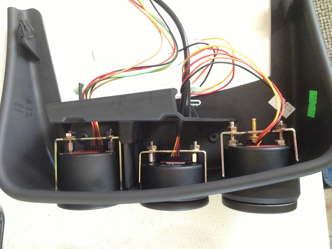 This is not from the van, but illustrates how its going to look.
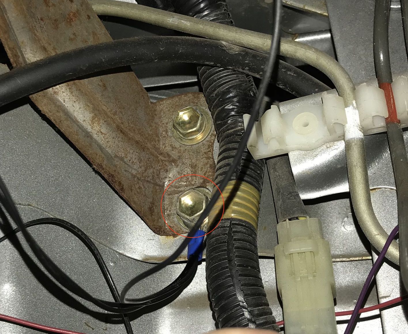 A nice ground location behind the dash to the right of the steering column.
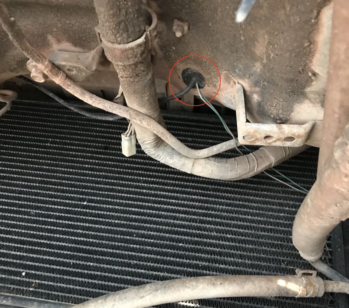 I ran my wiring through this plug from the interior, around the radiator, and to the engine.
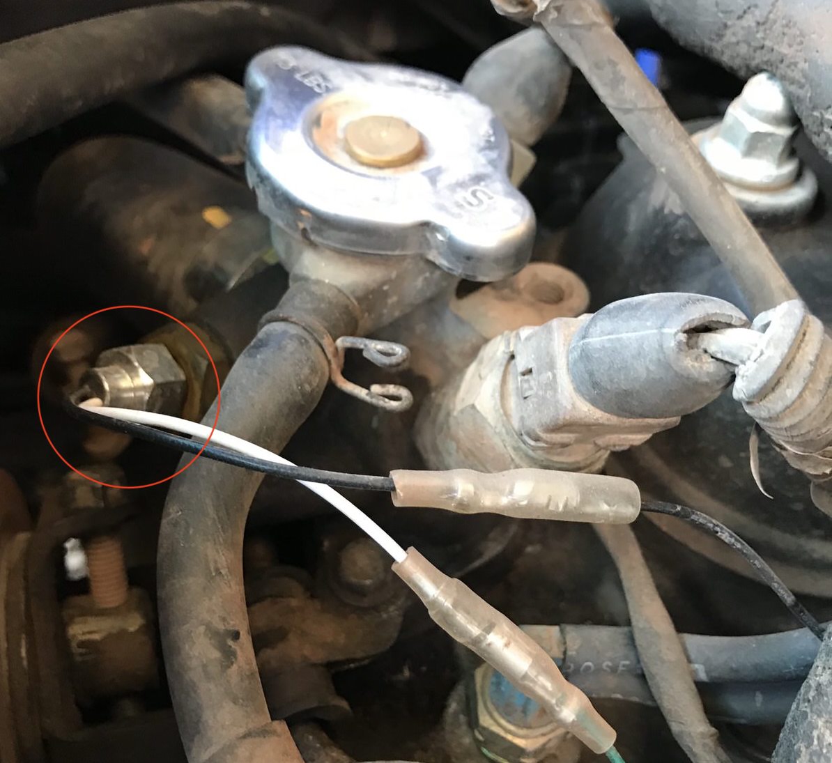 Water temp sensor plugged in at the fillter neck. If an open port is available on the block, it will giev a more accurate reading.
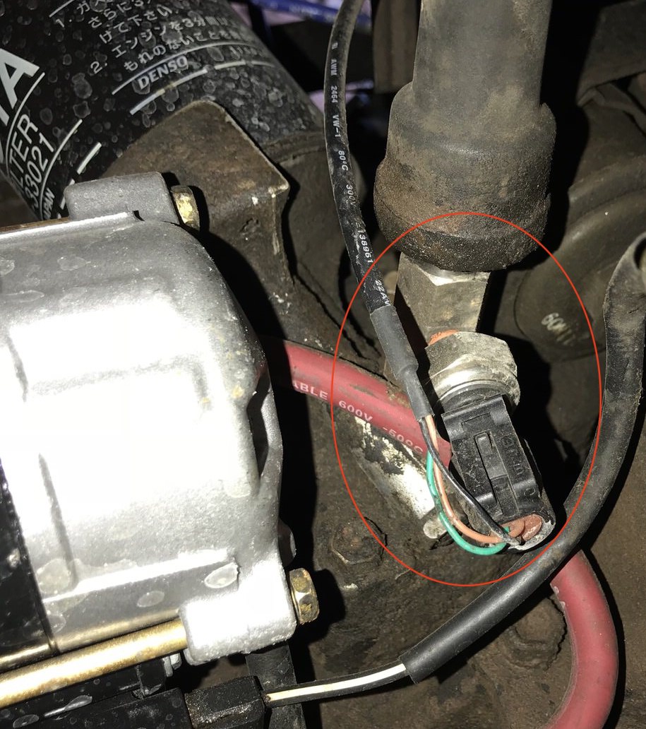 Oil pressure sensor with BSPT to NPT tee to retain the factory oil light functionality
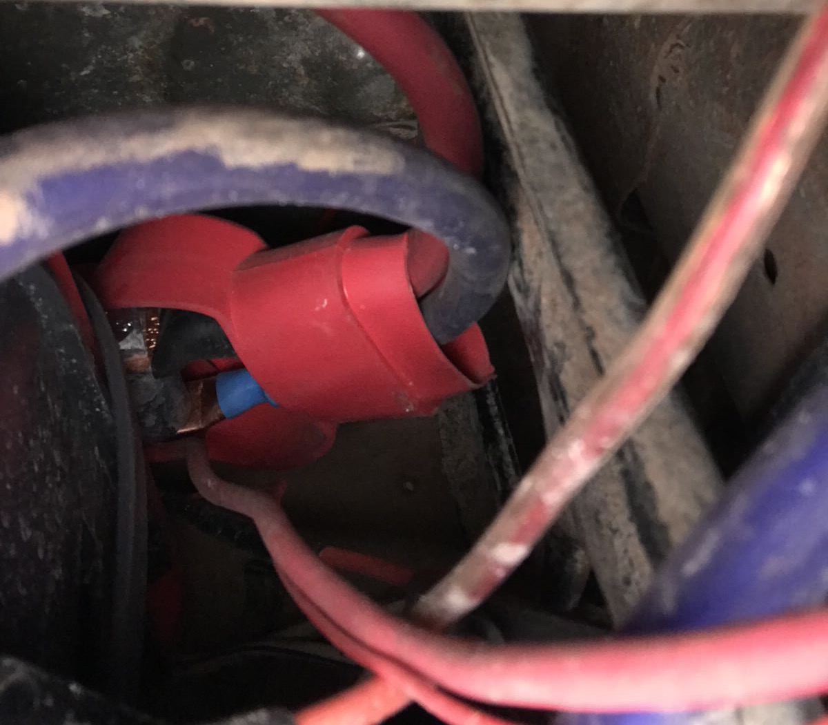 Run the positive cables up to the positive battery terminal
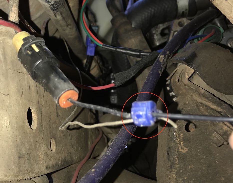 This works for now. I also used leftover speaker wire cause its all I had on hand!